
How to define the connection point for custom pipe clamp in order to build the AutoCAD Plant 3D Catalog
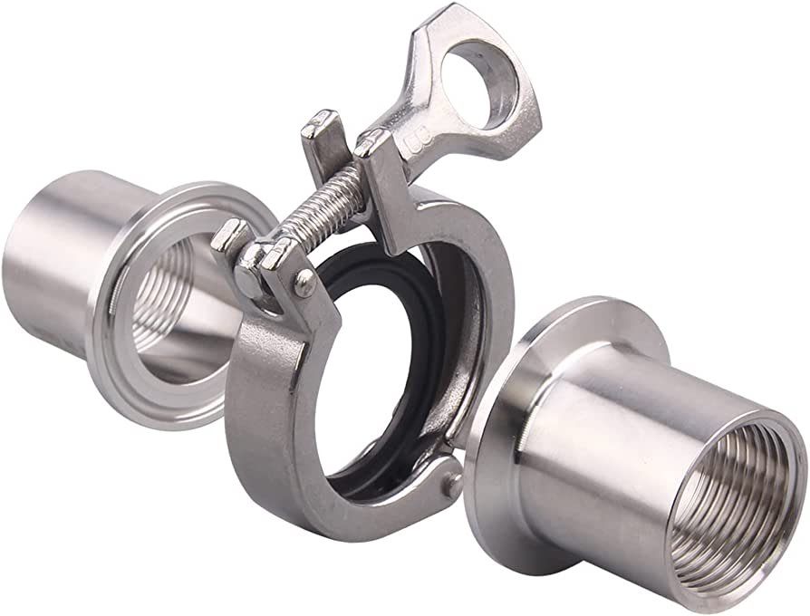
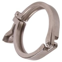
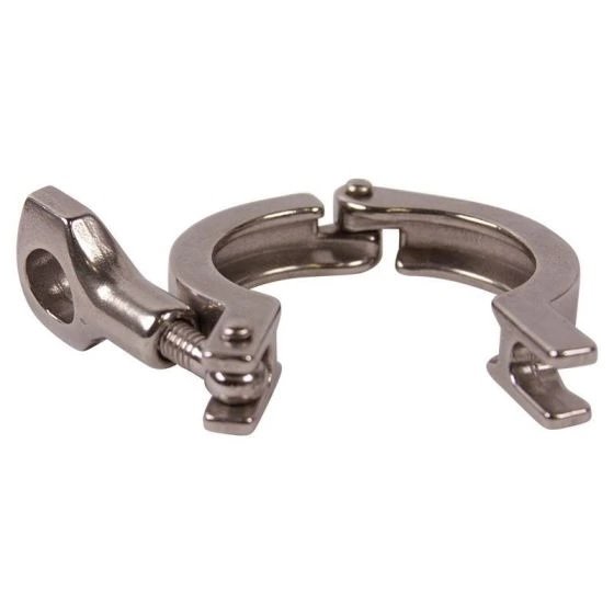
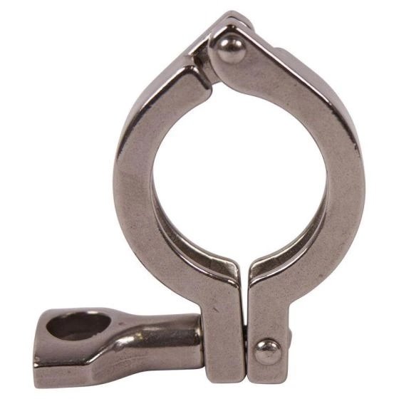
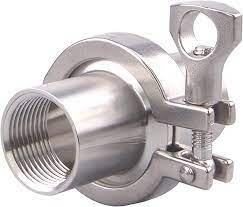
Tri-clamps are one of the most common types of pipe connections in the food, beverage, biotech, and pharmaceutical industries. This type of connection consists of a gasket compressed between two tri-clamp ferrules or flanges, which are mechanically compressed in place with a clamp. Tri-clamp fittings and gaskets are typically used in hygienic or sanitary fitting applications.
AutoCAD Plant 3D nowadays has become more popular and widely used by many engineering contractors, not only because of its easy-to-use software but also because it has the capability of building custom catalogs for pipes, fittings, and valves.
In this article, we just want to highlight the steps needed to define the connection points for a custom block-based tri-clamp.
1. Create the tri-clamp shapes with AutoCAD 3D primitives or convert them from other 3D CAD packages.
2. Create an AutoCAD block for the tri-clamp, align the tri-clamp with X-axis, color by block
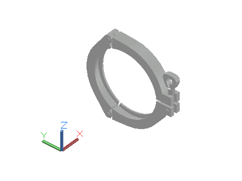
3. Tri-clamp has two connection points with the “Undefined_ET” End Type.
The connection point should be on the far side of the tri-clamp. The distance of the connection point from the near side of the tri-clamp can be calculated below:

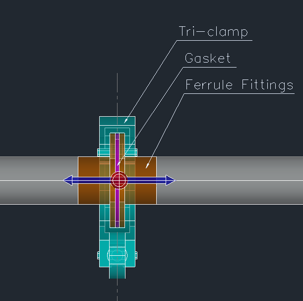
With this position of the defined connection point, when you reverse the connections of the fitting by using the “Flip Part” command, the fitting is still in the connected state.

This v.1.0.1content contains a metric version (metric Nominal Pipe Size and metric dimension) for Pipe, Fittings, Flanges, Gaskets, and VP200 accessories for PVC materials of the Hershey Valve manufacturer.
- All Pipe, Fittings, and VP Accessories components are parametric primitives.
- Engagement lengths are according to the vendor catalog.
- All items have their product codes are entered with the “Material code” & “Item code” fields.
1. Hershey Valve – CPVC Pipe and Fittings (Advanced Industrial Piping System)
http://www.hersheyvalve.com/downloadfiles/Hershey%20Valve-%20CPVC%20Catalog%202012.02.pdf
2. Hershey Valve – UPVC Pipe and Fittings (Industrial Piping System)
http://www.hersheyvalve.com/downloadfiles/HERSHEY%20VALVE-UPVC%20Pipe%20and%20Fittings%202011.pdf
3. Hershey Valve – VP200 Accessories series
http://www.hersheyvalve.com/downloadfiles/Hershey%20Valve-%20Valve%20catalog-%20VP-200%202013.07.pdf
Catalog components include:
- PIPE (SCH40 & SCH80)
- 90 ELBOW (SCH40 & SCH80)-SOCKET
- 90 ELBOW (SCH40 & SCH80)-THREAD
- 45 ELBOW (SCH40 & SCH80)-SOCKET
- COUPLING (SCH40 & SCH80)-SOCKET
- COUPLING (SCH40 & SCH80)-THREAD
- TEE (SCH40 & SCH80)-SOCKET
- TEE (SCH40 & SCH80)-THREAD
- CAP (SCH80)
- Y-TEE 45 (SCH80)
- RED. TEE (SCH80)
- RED. BUSHING (SCH80)
- RED. COUPLING (SCH80)
- CROSS (SCH80)-SOCKET
- ADAPTER (SCH80)
- COMPRESSION TEE
- COMPRESSION COUPLING
- T STRAINER – FLANGE (ANSI, JIS STANDARD)
- Y STRAINER – FLANGE (ANSI, JIS STANDARD)
- Y STRAINER – UNION (ANSI, JIS STANDARD)
- Y STRAINER – FLANGE (ANSI, JIS STANDARD)
- EXPANSION JOINT– FLANGE (ANSI, JIS STANDARD)
- EXPANSION JOINT– SOCKET (ANSI STANDARD)
- EXPANSION JOINT– THREAD (ANSI STANDARD)
- UNION– SOCKET (ANSI, JIS STANDARD)
- UNION– THREAD (ANSI, JIS STANDARD)
- FLANGE ONE PIECE– SOCKET (ANSI, JIS STD.)
- FLANGE ONE PIECE– THREAD (ANSI, JIS STD.)
- FLANGE VAN STONE– SOCKET (ANSI, JIS STD.)
- FLANGE VAN STONE– THREAD (ANSI, JIS STD.)
- BLIND FLANGE
- GASKET
GET IT NOW AT AUTODESK APP STORE:
DOWNLOAD


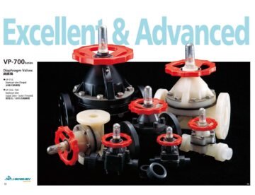
This v1.0.0 content pack contains the metric version (metric NPD and metric dimension) for the Valves of Hershey Valve manufacturer.
- All valve and actuator components are parametric primitives.
- Engagement lengths and flange dimensions are according to the vendor catalog.
- All items have their product codes entered in the “Material code” field.
Hershey Valves Catalog
http://www.hersheyvalve.com/downloadfiles/Hershey%20Valve%20-%20Catalog%202011.05.pdf
Catalog components include:
Material code / Description
VP-310,320,330,340 / Economy Single Union Ball Valve
VP-360,370 / Two-piece Ball Valve
VP-420,430 / Economy Swing Check (Foot) Valve
VP-440 / True Union Ball Check Valve
VP-450 / Swing Check Valve
VP-460,470 / Ball Check (Foot) Valve
VP-480,490 / Spring Check (Foot) Valve
VP-620 / Single Union Ball Valve
VP-640 / Double Union Ball Valve
VP-640 / Double Union Ball Valve (N1 Handle)
VP-680,690 / Pneumatic/Electric Actuator Double Union Ball Valve
VP-710 / Diaphragm Valve (Flange)
VP-720 / Diaphragm Valve (Spigot, Union, Socket, Thread)
VP-800 / Butterfly Valve (Handle Type)
VP-820 / Butterfly Valve (Gear Box)
VP-830 / Pneumatic Actuator Butterfly Valve
VP-840 / Electric Actuator Butterfly Valve
VP-900,910 / Compact Ball Valve
Contact Lavicas at info@lavicas.com for more details and requests.
Installation notes:
These catalogs are compatible with AutoCAD Plant 3D 2019 & higher versions. This installer will copy the catalog “Hershey Valves Catalog -Metric.pcat” into your content catalog location. The default location is: C:\AutoCAD Plant 3D 2023 Content\ CPak Common\ Hershey Valves Catalog -Metric.pcat
Uninstallation notes:
To uninstall this content pack, please go to Control Panel => Programs and Features => select the ” Hershey Valves Catalog -Metric ” => Uninstall
GET IT NOW AT AUTODESK APP STORE:
DOWNLOAD


This v.1.0.1 content contains an imperial version (imperial Nominal Pipe Size and imperial dimension) for Pipe, Fittings, Flanges, Gaskets, and VP200 accessories for PVC materials of the Hershey Valve manufacturer.
- All Pipe, Fittings, and VP Accessories components are parametric primitives.
- Engagement lengths are according to the vendor catalog.
- All items have their product codes are entered with the “Material code” & “Item code” fields.
1. Hershey Valve – CPVC Pipe and Fittings (Advanced Industrial Piping System)
http://www.hersheyvalve.com/downloadfiles/Hershey%20Valve-%20CPVC%20Catalog%202012.02.pdf
2. Hershey Valve – UPVC Pipe and Fittings (Industrial Piping System)
http://www.hersheyvalve.com/downloadfiles/HERSHEY%20VALVE-UPVC%20Pipe%20and%20Fittings%202011.pdf
3. Hershey Valve – VP200 Accessories series
http://www.hersheyvalve.com/downloadfiles/Hershey%20Valve-%20Valve%20catalog-%20VP-200%202013.07.pdf
Catalog components include:
- PIPE (SCH40 & SCH80)
- 90 ELBOW (SCH40 & SCH80)-SOCKET
- 90 ELBOW (SCH40 & SCH80)-THREAD
- 45 ELBOW (SCH40 & SCH80)-SOCKET
- COUPLING (SCH40 & SCH80)-SOCKET
- COUPLING (SCH40 & SCH80)-THREAD
- TEE (SCH40 & SCH80)-SOCKET
- TEE (SCH40 & SCH80)-THREAD
- CAP (SCH80)
- Y-TEE 45 (SCH80)
- RED. TEE (SCH80)
- RED. BUSHING (SCH80)
- RED. COUPLING (SCH80)
- CROSS (SCH80)-SOCKET
- ADAPTER (SCH80)
- COMPRESSION TEE
- COMPRESSION COUPLING
- T STRAINER – FLANGE (ANSI, JIS STANDARD)
- Y STRAINER – FLANGE (ANSI, JIS STANDARD)
- Y STRAINER – UNION (ANSI, JIS STANDARD)
- Y STRAINER – FLANGE (ANSI, JIS STANDARD)
- EXPANSION JOINT– FLANGE (ANSI, JIS STANDARD)
- EXPANSION JOINT– SOCKET (ANSI STANDARD)
- EXPANSION JOINT– THREAD (ANSI STANDARD)
- UNION– SOCKET (ANSI, JIS STANDARD)
- UNION– THREAD (ANSI, JIS STANDARD)
- FLANGE ONE PIECE– SOCKET (ANSI, JIS STD.)
- FLANGE ONE PIECE– THREAD (ANSI, JIS STD.)
- FLANGE VAN STONE– SOCKET (ANSI, JIS STD.)
- FLANGE VAN STONE– THREAD (ANSI, JIS STD.)
- BLIND FLANGE
- GASKET
GET IT NOW AT AUTODESK APP STORE:
DOWNLOAD


Flanges are designed to remain leak-free under hydrostatic test pressure (cold condition) and under operating pressure (hot condition). Flange Leakage is a function of the relative stiffnesses of the flange, gasket, and bolts.
Flange leakage is considered a serious issue in the process plant operation. It has a tremendous potential to cause a severe hazard in the process plants. Therefore, flange leakage needs to be investigated during the design stage to reduce the possibility of leakage during the testing and operation stage.
The design of ASME flanges (ASME B16.5, B16.47) does not take into account the external bending moment and axial force in the pipe. This will cause a wire drawing effect on the mating surface of the flange. Therefore, additional flexibility is to be provided when a flange joint is located near a spot with a high bending moment. So, flange leakage checking is really required.
ASME Piping Flanges (ASME B16.5, B16.47 …) are designed in accordance with ASME Boiler and Pressure Vessel Code, Section VIII, Division 1, Appendix 2, but using allowable stress and temperature limits of ASME B 31.3 code.
In general practice, the following cases need to be considered for flange leakage:
- Flanges with pressure rating 600 and above
- Flanges with pressure rating 300 and above, pipe size 16 inches and above
- Pipe flanges carrying category M fluid service
- Pipe flanges carrying hydrogen or other flammable fluid
- Flanges in PSV lines with NPS 4 inches and above
- Flanges in jacketed piping
- Flanges with stress analysis output of very high bending moment
There are various methods for determining if the flange joint is leaking, including:
- Pressure Equivalent method based on ASME B 16.5 P-T rating
- ASME BPVC Sec VIII Div.1 Appendix 2 method.
- NC 3658.3 method
In this article, we’ll explore into how to check for flange leakage by ASME BPVC Sec VIII Div.1 Appendix 2 method together with the application of pressure equivalent method to take into account the external force and moment.
Kellogg Method convert piping axial forces and bending moments into an equivalent pressure on the flange.
Peq = 16Mb /πG³+ 4Fa/πG²+ Pd
Where:
Peq = total equivalent pressure
Mb = calculated bending moment on flange
G = diameter of effective gasket reaction
Fa = axial force of flange
Pd = design pressure
Before we go to a thorough calculation, we need to point out here two distinct scenarios for the gasket group:
- case 1: for spiral-wound and ring joint gasket
- case 2: for the full-face gasket.
1. For spiral-wound and ring joint gasket.

K = ratio of the outside diameter of the flange to the inside diameter of the flange = A /B
K²(1 + 8.55246 log₁₀K)-1
T =
(1.04720 + 1.9448 K²)(K-1)
K² (1 + 8.55246 log₁₀K) -1
U =
(1.36136(K² – 1)(K – 1)
1 K² log₁₀K
Y = (0.66845+5.71690 )
K -1 K² – 1
K² + 1
Z =
K² – 1
The required bolt load for the operating conditions W1:
Wm1 = H + Hp = 0.785 G² Peq + (2b x 3.14GmP)
m = gasket factor
The minimum initial bolt load required for this purpose Wm2:
Wm2= 3.14bGy
where b = b₀ when b₀ ≤ 1⁄4 inches (6 mm) and b = Cb√b₀ when b₀ > 1⁄4 inches (6 mm)
The total required bolt area shall be Am = max(Wm1/Sb, Wm2/Sa), and the Actual bolt area Ab >= Am
Sa = allowable bolt stress at atmospheric temperature
Sb = allowable bolt stress at design temperature
Flange design bolt load:
– For operating condition: W = Wm1
– For gasket seating condition: W = (Am + Ab) Sa /2
Flange moment and stress:
– For operating condition:
hD = R + 0.5g1, hG = (C-G)/2, ht = (R+g1+hG) /2
H = total hydrostatic end force = 0.785G²Peq
HD = hydrostatic end force on area inside of flange = 0.785B²Pd
HG = W – H
HT = H – HD
MD = hD * HD
MG = hG * HG
MT = hT * HT
Mᴏ = MD + MG + MT
Longitudinal hub stress SH = fMᴏ / Lg1²B
Radial flange stress SR = (1.33tₑ +1)Mᴏ /Lt²B
Tangential flange stress ST = YMᴏ/t²B – ZSR
f = hub stress correction factor for integral flanges
L = (tₑ +1)/T + t³/ d
t = flange thickness
d = Uhᴏ gᴏ²/V
e = F / hᴏ
F = flange factor
hᴏ = √Bgᴏ
– For gasket seating condition:
Mᴏ = W(C-G)/2
Longitudinal hub stress SH = fMᴏ / Lg1²B
Radial flange stress SR = (1.33 tₑ +1)Mᴏ / Lt²B
Tangential flange stress Sᴛ = YMᴏ/t²B – ZSR
f = hub stress correction factor for integral flanges
L = (tₑ +1)/T + t³/d
t = flange thickness
d = Uhᴏgᴏ²/V
e = F /hᴏ
F = flange factor
hᴏ = √Bgᴏ
2. For full-face gasket.

b = (C-B)/4
G = C- 2hɢ
hɢ = (C-B)(2B+C)/6(B+C)
hɢ’ = (A-C)(2A+C)/6(A+C)
hɢ” = hɢ*hɢ’/(hɢ + hɢ’)
The required bolt load for the operating conditions Wm1:
Wm1 = H + Hp = 0.785G²Peq+(2bx3.14GmP)(1+hɢ/hɢ’)
m = gasket factor
The minimum initial bolt load required for this purpose is Wm2:
Wm2= 3.14bGy(1+hɢ/hɢ’)
Total required bolt area Am = max(Wm1/Sb,Wm2/Sa), and Actual bolt area Ab >= Am
Sa = allowable bolt stress at atmospheric temperature
Sb = allowable bolt stress at design temperature
Flange design bolt load:
– For operating condition: W = Wm1
– For gasket seating condition: W = (Am+Ab) Sa /2
Flange moment and stress:
– For operating condition:
hᴅ =(C-B)/2, hɢ = (C-G)/2, hᴛ =((C-B)/2+hɢ) /2
H = total hydrostatic end force = 0.785G²Peq
Hᴅ = hydrostatic end force on area inside of flange = 0.785B²Pd
Hɢ = W – H
Hᴛ = H- Hᴅ
Mᴅ = hᴅ * Hᴅ
Mᴛ = hᴛ * Hᴛ
Mᴏ = Mᴅ + Mᴛ
Longitudinal hub stress SH = fMᴏ/Lg1²B
Radial flange stress SR = (1.33tₑ+1)Mᴏ/Lt²B
Tangential flange stress ST =YMᴏ /t²B – ZSR
Radial stress at bolt circle SRAD = 6Mᴏ/t²(πC-nd1)
f = hub stress correction factor for integral flange
L = (tₑ +1)/T + t³/ d
t = flange thickness
d = Uhᴏgᴏ²/V
e = F/hᴏ
F = flange factor
hᴏ = √Bgᴏ
n = number of bolt
d1 = bole hole diameter
– For gasket seating conditions:
Mᴏ = Hɢ * hɢ”
Longitudinal hub stress SH = fMᴏ/Lg1²B
Radial flange stress SR = (1.33tₑ+1)Mᴏ/Lt²B
Tangential flange stress ST = YMᴏ/t²B-ZSR
Radial stress at bolt circle SRAD = 6Mᴏ/t²(πC-nd1)
f = hub stress correction factor for integral flange
L = (tₑ +1)/T+t³/d
t = flange thickness
d = Uhᴏgᴏ²/V
e = F/hᴏ
F = flange factor
hᴏ = √Bgᴏ
n = number of bolt
d1 = bole hole diameter
Database inputs for Flange Leakage App:
- Piping database ASME B36.10, B36.19
- Flange dimension ASME B16.5,ASME B16.47
- Gasket dimension ASME B16.20, ASME B16.21
- Flange specification and allowable stress as ASME B31.3
- Bolt specification and allowable stress as ASME B31.3
- Gasket properties as ASME Section VIII div.1 and Flexitallic catalog